
Print-in-Place Hinges and Moving Assemblies in SLS Nylon
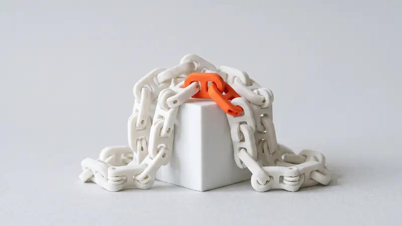
Selective laser sintering prints parts inside a bed of powder that supports them on every side, so it needs no support structures. That makes it possible to print hinges, chains, ball joints and other mechanisms already assembled, in one print job, with no assembly afterwards. This guide explains the clearances, the powder-escape rules and the design choices that make print-in-place assemblies in PA 12 move freely.
Why SLS is made for print-in-place
In filament and resin printing, every overhang needs support, and supports inside a hinge are almost impossible to remove. In SLS the part grows inside a bed of PA 12 powder. The powder that is not fused stays loose around the part and carries it, so the printer can produce closed loops, interlocking links and pins inside knuckles without any support. After printing, the loose powder is removed and the mechanism moves.
Typical print-in-place parts are hinges and hinged lids, chains and cable carriers, ball joints and articulated fingers for grippers, rotating knobs and dials, captive screws and clips, and demonstration models with moving parts. The practical gain: no assembly, no small parts to lose, and a mechanism that is ready when it arrives.
The two rules: gap and powder escape
Rule 1: at least 0.5 mm gap
During printing, powder grains next to a fused surface partly melt and stick to it. If two moving surfaces are too close, the grains between them bond to both and the joint is fused. A gap of at least 0.5 mm between all moving surfaces is our starting guideline for laser-sintered PA 12. Larger parts and long, narrow gaps benefit from more.
| Situation | Starting gap | Note |
|---|---|---|
| Small hinge, short gap, open to the outside | 0.5 mm | The minimum we recommend |
| Long or curved gap (pin in a long knuckle) | more than 0.5 mm | Powder has a longer way out |
| Ball joint | more than 0.5 mm | Spherical gaps trap powder easily |
| Large flat surfaces sliding on each other | more than 0.5 mm | Large areas can warp slightly |
These are starting points, not guarantees. For a critical mechanism, print a small test version first; with an instant price, a test costs little.
Rule 2: the powder must be able to get out
Every gap is full of powder when the part leaves the printer. Depowdering and glass-bead blasting remove it, but only if it can reach the outside. A gap that is open on both ends cleans out easily. A closed pocket or a long blind channel keeps its powder, and a joint full of compacted powder does not move.
- Open every joint to the outside on at least one side, better on two.
- Avoid blind holes around pins; let the pin channel run through.
- Add escape holes to closed volumes; the calculator detects enclosed cavities when you upload the model.
- Keep gaps short and straight where you can.
Designing a print-in-place hinge
A print-in-place hinge consists of knuckles on both halves and a pin that belongs to one half and runs through the other. A few details make the difference between a hinge that moves on the first try and one that has to be broken free:
- Chamfer or cone the pin ends so the pin is captured but the gap stays open at the ends.
- Keep the gap uniform around the pin and between the knuckle faces.
- Give the pin enough diameter to carry the load; thin pins in nylon bend. If the hinge is loaded, consider a hole for a metal pin instead.
- Add an angle stop if the lid should not over-rotate.
- Avoid contact areas that are large and flat; they need more clearance than small cylindrical ones.
A print-in-place hinge does not depend on the material bending, so it usually lasts far longer than a living hinge in SLS nylon. The price is some play and more space for the knuckles.
Chains, ball joints and other mechanisms
Chains and cable carriers
Interlocking links are the classic SLS showcase. Each link needs the 0.5 mm gap to its neighbors on all sides, and every link should be open enough for the powder to fall out.
Ball joints
A ball inside a socket is the hardest case, because the spherical gap traps powder. Open the socket generously, add slots, and start with a larger gap than for a hinge. If the joint must hold a position by friction, test it: the friction after depowdering is hard to predict.
Rotating parts and dials
A knob captured on a shaft works well if the shaft has a shoulder or a cone to hold the knob and the gap stays open on the outside. For a detent feel, add a small flexible tongue rather than relying on a tight fit.
Orientation and accuracy
Print preparation chooses the orientation for the whole print job, and moving parts work in any orientation as long as the gaps are respected. Layers are about a tenth of a millimeter thick (EOS lists 0.12 mm for the PA 2200 process), so curved surfaces show fine steps that slightly increase friction. The general tolerance we design to is ±0.3 % with a lower limit of ±0.3 mm; more in SLS tolerances and clearances.
After printing: depowdering, blasting, dyeing
Our parts are depowdered, then glass-bead blasted and polished in a DyeMansion Powershot DUAL, included in the price. Blasting clears the gaps and smooths the contact surfaces; according to DyeMansion, the process compacts the surface without removing material, so the designed gap stays as it is. Moving the mechanism a few times after delivery frees it fully. If you choose a color, dyeing with TCN liquid dyes colors the surface layer without adding a coating, so it does not close the gaps. Read more about the steps in SLS post-processing and surface finish.
Checklist
- At least 0.5 mm gap between all moving surfaces.
- Every gap and cavity open to the outside; no blind pin holes.
- Pin ends chamfered or coned so the pin is captured.
- Angle stops where rotation must be limited.
- Load-bearing hinges: thicker pin or a hole for a metal pin.
- Uploaded as one model; check the cavity warning in the calculator.
- Critical mechanism: a small test version first.
For mechanisms that carry load, need a defined feel or are part of a product, the specialists at prototype.builders can review the design intent with you.
Frequently asked questions
What does print-in-place mean?
A mechanism such as a hinge, chain or ball joint is printed already assembled, with a small gap between the moving parts. After printing, the loose powder is removed from the gap and the parts move freely without any assembly.
What gap do print-in-place parts need in SLS?
Use a gap of at least 0.5 mm between moving surfaces. Smaller gaps risk fusing the parts together, because powder next to the hot surfaces partly sinters and sticks.
Why is SLS good for print-in-place parts?
The unfused powder supports the parts during printing, so no support structures have to be removed from inside the joint. Any orientation and any nested geometry are possible as long as the powder can get out.
Can trapped powder stay inside the joint?
Yes, if the joint is closed. Loose powder must be able to leave every gap and cavity. Open the joint to the outside, avoid long blind channels and add escape holes to closed volumes. The calculator detects enclosed cavities when you upload the model.
Will a print-in-place hinge have play?
Yes, a little. The gap needed to keep the parts apart during printing becomes play after depowdering. Where play matters, design a separate pin or bushing, or ask for design support.
Do I need to upload separate files for the moving parts?
No. A print-in-place assembly is uploaded as one model. The calculator checks that it fits the 200 × 250 × 330 mm chamber and prices it as one part.
Get an instant price
Upload STEP or STL files to the calculator and see the price of your parts in seconds: white Nylon PA 12, blasting and polishing included, optional dyeing in 61 colors, three delivery speeds. From there you send the order preview for confirmation.
Another material, an NDA or a large series? Write to us. For design help and prototype development see prototype.builders.
Get an instant price